Sign In
Upload
Manuals
Brands
HP Manuals
Monitor
1345A
HP 1345A Manuals
Manuals and User Guides for HP 1345A. We have
1
HP 1345A manual available for free PDF download: Operating And Service Manual
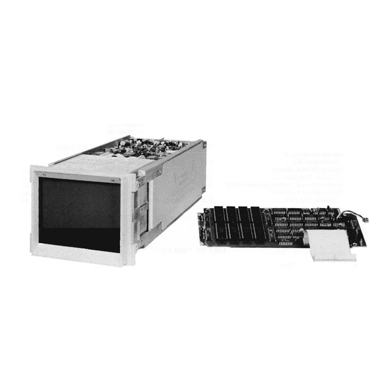
HP 1345A Operating And Service Manual (184 pages)
Digital Display
Brand:
HP
| Category:
Monitor
| Size: 35.97 MB
Table of Contents
Table of Contents
5
General Information
9
Introduction
9
Specifications
9
Safety Considerations
9
Instruments Covered by Manual
9
Description
9
Option 323
15
Option 325
15
1-28. Recommended Test Equipment
15
Installation
17
Introduction
17
Initial Inspection
17
Preparation for Use
17
Power Connector
17
I/O Connector
17
Analog Outputs (X-Y-Z)
17
Introduction .0
17
Figure
17
Operating Environment
18
Mechanical Considerations
18
Ambient Temperature Measurement
18
1345A 110 Connector
18
Mounting Configuration
19
Storage and Shipment
19
Packaging
19
Definition of Moments of Inertia and Center of Gravity
20
Major Signal Line Definitions
22
Operation
23
Introduction
23
Operating Considerations
23
Functional Blocks of the 1345A
23
User Instrument Requirements
24
1345A Functional Block Diagram
24
Block Diagram of an Example System Incorporating the 1345A
24
Handshake Timing
25
LRFD and LDA V (Ready for Data, Data Valid) Handshake
25
Instructions
26
Binary to HEX Conversion
26
Set Condition Examples in HEX
27
Vector Drawing Area
27
Vector Plotting
28
Vector Defined by Endpoints
28
Two Horizontal Lines on the Display
28
Graph Mode Example
31
1345A Modified ASCII Character Set
32
Text Command Bit Pattern
34
1345A Character Display Capabilities
34
Example of Character Spacing
34
Character Rotation
34
Refresh Requirements
36
Potpourri
36
Character Borders
36
1345A Digital Display
37
Simple Interface
37
1345A Interfacing Techniques
37
Figure
37
Single Processor Interface
37
DMA Interface
38
Smart Interface
39
Operation for Option 704
39
Description
39
Example Smart Interface
39
Vector Memory Interface (Option 704)
39
Vector Memory Management
40
Example Instrument with Memory Option 704
40
Reading the Vector Memory
41
Refresh
41
Introduction
41
Synchronous Refresh Example
42
Asynchronous Refresh Example
42
Picture Complexity
43
1345A Capabilities for Character and Vector Combinations
44
Vector Drawing Time Calculations
44
A Spectrum Analyzer Presentation
45
A Smith Chart Presentation
45
Additional 1345A Example Displays
46
Vector Memory Read and Write Signal
47
Timing Specifications
47
Read Command Timing
47
Write Command Timing
48
Programming
49
Potpourri
50
Vector Memory Map
51
Performance Tests
53
Introduction
53
Equipment Required
53
Calibration Cycle
53
Performance Test Procedures
53
Rear Panel Power Connections
54
Display of Properly Calibrated Pattern
54
Display of Uncalibrated Verification Pattern
54
1345A Command Check-Out
55
Memory Test Fail
56
Adjustments
57
5-1. Introduction
57
5-3. Safety Requirements
57
5-5. Equipment Required
57
Adjustment
57
5-10. Adjustment Procedures
57
Stroke Generator and
57
5-I. 1345A Assembly Location Identification
58
5-11. Low Voltage Power Supply Adjustments
59
Low Voltage Power Supply Adjustment Locations
59
Adjustment
60
High Voltage Power Supply Adjustment Locations
60
Pattern Adjustment
61
Primary Test Pattern Adjustment
61
Primary Test Pattern Adjustment Locations
61
Test Pattern for Stroke Length Adjustment
62
Stroke Generator Adjustment
63
Stroke Generator and Stroke Length Adjustment Locations
63
Figure
63
5-15. Stroke Intensity Adjustment
64
5-16. Focus Adjustment and Resolution Check
64
Service Sheet
64
Test Pattern for Focus Adjustment
65
Stroke Intensity and Focus
66
Writing Rate Adjustment
67
Astigmatism and Pattern Adjustment
67
5-19. Auxiliary X-Y-Z Output Check
67
X-Amplifier Auxiliary Output
67
Table
67
Replaceable Parts
68
Introduction
68
Abbreviations
68
Replaceable Parts List
68
Ordering Information
68
Direct Mail Order System
68
List of Manufacturers' Codes
85
Manual Changes
86
Introduction
86
Manual Change Instructions
86
Service Sheet 6, Memory
86
Z-Amplifier Auxiliary Output
112
Replacement for A-2 Parts List
127
Replacement for A-4 Parts List
128
Replacement for A-2 Parts List
128
Service
138
Introduction
138
Theory of Operation
138
DC Voltages and Waveforms
138
Assembly Removal
138
Preventive Maintenance
138
Service Sheet Quick Reference
138
Logic Symbology
141
Principles of Operation
142
Vector Processor Control Board
142
Output Amplifiers
142
Service Sheet 1, Block Diagram
146
Service Sheet 2, Vector Processor (A2)
151
Advertisement
Advertisement
Related Products
HP 1311B
HP 1317A
HP 1349A
HP 1349 D
HP 1331A
HP 1332A
HP 15-inchhp55
HP 1706
HP 19-inch LP1965
HP Passport 1912nc
HP Categories
Desktop
Laptop
Server
Monitor
Switch
More HP Manuals
Login
Sign In
OR
Sign in with Facebook
Sign in with Google
Upload manual
Upload from disk
Upload from URL