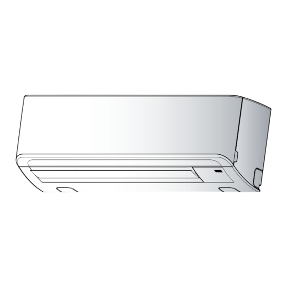
Summary of Contents for Toshiba RAS-16N3KV2 Series
- Page 1 INSTALLATION MANUAL AIR CONDITIONER (SPLIT TYPE) Indoor unit Outdoor unit RAS-10, 13, 16N3KV2 Series RAS-10, 13, 16N3AV2 Series 1110251276 Cover 1110251276.indd 1 Cover 1110251276.indd 1 11/26/12 4:33 PM 11/26/12 4:33 PM...
-
Page 2: Table Of Contents
CONTENTS PRECAUTIONS FOR SAFETY ...............................1 INSTALLATION DIAGRAM OF INDOOR AND OUTDOOR UNITS ....................2 Optional Installation Parts ................................2 INDOOR UNIT ....................................3 Installation Place ..................................3 Cutting a Hole and Mounting Installation Plate ...........................3 Wiring Connection ..................................3 How to Connect Remote Controller for Wire Operation ......................4 ... -
Page 3: Precautions For Safety
• Appliance shall be installed in accordance with national wiring regulations. If you detect any damage, do not install the unit. Contact your TOSHIBA dealer immediately. • Do not use any refrigerant different from the one specifi ed for complement or replacement. -
Page 4: Installation Diagram Of Indoor And Outdoor Units
108 mm Gas side : Ø9.52 mm 28 mm Air inlet (RAS-10, 13N3KV2 Series) each : Ø12.70 mm (RAS-16N3KV2 Series) Pipe insulating material (polyethylene foam, 6 mm thick) Air outlet 90 mm Putty, PVC tapes 600 mm each Drain outlet 1110251276-EN.indd 2... -
Page 5: Indoor Unit
INDOOR UNIT INDOOR UNIT When the installation plate is directly mounted Installation Place on the wall • A place which provides the spaces around the indoor unit as shown in the 1. Securely fi t the installation plate onto the wall by screwing it in the upper and diagram lower parts to hook up the indoor unit. -
Page 6: How To Connect Remote Controller For Wire Operation
70 mm Terminal block * Wire size 28-22AWG or 0.08-0.32 mm Cord Outer diameter not over 4.7 mm, clamp Terminal cover control wire length less than 30 m. 5 mm Screw Notch for wire out Connecting cable Screw Earth line 100 mm 10 mm Tighten fi... -
Page 7: Piping And Drain Hose Installation
Battery cover 2) Firmly insert the drain cap. Screw Tighten fi rmly but not over No gap 0.15 N.m (0.02 kgf.m) Do not apply lubricating oil (refrigerant machine oil) when inserting the drain cap. Application causes deterioration and drain leakage of the plug. Insert a hexagon wrench (4 mm). -
Page 8: Indoor Unit Fixing
Do not form the Indoor Unit Fixing Do not rise the drain hose into drain hose. a wavy shape. 1. Pass the pipe through the hole in the wall and hook the indoor unit on the 50 mm installation plate at the upper hook. or more 2. -
Page 9: Evacuating
Tightening connection Compound pressure gauge Pressure gauge –101 kPa (–76 cmHg) Align the centers of the connecting pipes and tighten the fl are nut as far as Manifold valve possible with your fi ngers. Then tighten the nut with a spanner and torque Handle Hi wrench as shown in the fi... -
Page 10: Wiring Connection
RAS-10N3KV2 RAS-13N3KV2 RAS-16N3KV2 Wiring Connection Model Series Series Series Power source 50Hz, 220 – 240 V Single phase Maximum running current 8.5A 9.1A 11.0A 1. Remove the valve cover from the outdoor unit. 2. Connect power cord to the terminal block L, N and Circuit breaker 11.0A 12.0A... - Page 11 Cover back 1110251276.indd 1 Cover back 1110251276.indd 1 11/26/12 4:32 PM 11/26/12 4:32 PM...
- Page 12 Cover back 1110251276.indd 2 Cover back 1110251276.indd 2 11/26/12 4:32 PM 11/26/12 4:32 PM...


