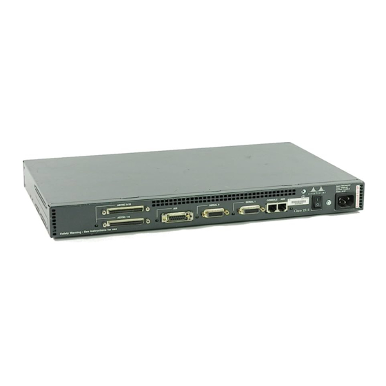
Cisco 2500 Series Installing Manual
Installing cisco ac and dc power supplies in cisco 2500 series routers
Hide thumbs
Also See for 2500 Series:
- User manual (92 pages) ,
- Installation and configuration manual (81 pages) ,
- Deployment manual (23 pages)
Advertisement
Quick Links
Doc. No.
78-4144-01
Installing Cisco AC and DC Power Supplies in
Cisco 2500 Series Routers
Product Numbers: PWR-2500-AC=, PWR-2500-DC=
This document describes how to replace the AC or DC power supply in Cisco 2500 series routers.
The AC and DC power supplies are spare parts items. The replacement of the power supply requires
removing the existing power supply and installing the replacement power supply. This procedure
does not apply to the Cisco 2517, 2518, or 2519 versions of the Cisco 2500 series routers.
This document includes the following sections:
•
Required Tools and Equipment, page 2
•
Removing the Cover, page 2
•
•
•
Replacing the Cover, page 6
•
Obtaining Service and Support, page 11
•
Cisco Connection Online, page 11
Warning
Before you work on any equipment, you must be aware of the hazards involved with the electrical
circuitry and familiar with standard practices for preventing accidents. (To see translated versions of
this warning, refer to the Regulatory Compliance and Safety Information document that
accompanied the router.)
Warning
equipment. (To see translated versions of this warning, refer to the Regulatory Compliance and
Safety Information document that accompanied the router.)
Corporate Headquarters
Cisco Systems, Inc.
170 West Tasman Drive
San Jose, CA 95134-1706
USA
Copyright © 1997
Cisco Systems, Inc.
All rights reserved.
This waning symbol means danger. You are in a situation that could cause bodily injury.
Only trained and qualified personnel should be allowed to install or replace this
1
Advertisement

Summary of Contents for Cisco 2500 Series
-
Page 1: Table Of Contents
Cisco 2500 Series Routers Product Numbers: PWR-2500-AC=, PWR-2500-DC= This document describes how to replace the AC or DC power supply in Cisco 2500 series routers. The AC and DC power supplies are spare parts items. The replacement of the power supply requires removing the existing power supply and installing the replacement power supply. -
Page 2: Required Tools And Equipment
Take the following steps to remove the chassis cover: Step 1 Power OFF the router. Step 2 Attach your ESD-preventive wrist strap. Step 3 Disconnect all cables from the rear panel of the router. 2 Installing Cisco AC and DC Power Supplies in Cisco 2500 Series Routers... -
Page 3: Removing Ac And Dc Power Supplies
(See Figure 2.) This screw secures the power supply to the chassis. Flat-blade screwdriver Slot Screw Slot Top section Bottom section Rear Left end toward you Installing Cisco AC and DC Power Supplies in Cisco 2500 Series Routers Removing AC and DC Power Supplies Front... - Page 4 Disconnecting the Power Connector Push the loosened power supply backward and lift it out of the chassis. (See Figure 4.) Step 3 4 Installing Cisco AC and DC Power Supplies in Cisco 2500 Series Routers AC power supply Power connector...
-
Page 5: Installing Ac And Dc Power Supplies
(See Figure 6.) AC power supply Stations Patch cables Lobe cables Stations Installing Cisco AC and DC Power Supplies in Cisco 2500 Series Routers Installing AC and DC Power Supplies T oken Ring Switch Stations T oken Ring Switch Stations... -
Page 6: Replacing The Cover
Referring to Figure 8, press the two chassis sections together and ensure the following: • • • 6 Installing Cisco AC and DC Power Supplies in Cisco 2500 Series Routers Power connector Fan connector The top section fits into the rear of the bottom section. (See A in Figure 8.) The bottom section fits into the front of the top section. - Page 7 This completes the procedure for installing AC and DC power supplies. If you have questions or need assistance, see the section “Obtaining Service and Support.” Installing Cisco AC and DC Power Supplies in Cisco 2500 Series Routers Top section Bottom section...
-
Page 8: Connecting The Dc Power Supply
(line to L), and negative to negative (neutral to N). Note that the ground wire should always be connected first and disconnected last. (To see translated versions of this warning, refer to the Regulatory Compliance and Safety Information document that accompanied your router.) 8 Installing Cisco AC and DC Power Supplies in Cisco 2500 Series Routers Design Specification... - Page 9 ON position. (To see translated versions of this warning, refer to the Regulatory Compliance and Safety Information document that accompanied your router. Installing Cisco AC and DC Power Supplies in Cisco 2500 Series Routers Connecting the DC Power Supply...
- Page 10 Figure 10 Power Requirements and System Identifier Label Sheet If the power supply in the Cisco 2500 series router is being converted from DC to AC, simply Note remove the Power Requirements and System Identifier labels from the rear panel of the router chassis.
-
Page 11: Obtaining Service And Support
Note The System Identifier label shown in Figure 11 shows the Cisco 2520 DC system label for demonstration purposes. Place the appropriate label for your specific model of Cisco 2500 series router in place of this label. Remove the System Identifier label from the sheet of labels included with the power Step 3 supply. - Page 12 ForeSight, Grand, Grand Junction, Grand Junction Networks, the Grand Junction Networks logo, HSSI, IGRP, IPX, Kalpana, the Kalpana logo, LightStream, MultiNet, MultiWare, OptiClass, Personal Ethernet, Phase/IP, RPS, StrataCom, TGV, the TGV logo, and UniverCD are registered trademarks of Cisco Systems, Inc. All other trademarks, service marks, registered trademarks, or registered service marks mentioned in this document are the property of their respective owners.


