Table of Contents
Advertisement
Quick Links
PRODUCT NAME
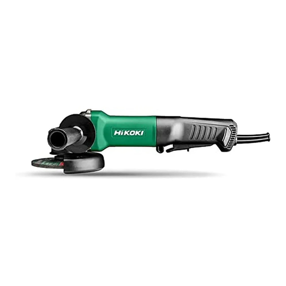
Disc Grinder
Models 115 mm (4-1/2")
125 mm (5")
CONTENTS
REPAIR GUIDE ---------------------------------------------------------------------------------------------------------------- 1
1. Precautions on disassembly and reassembly ----------------------------------------------------------- 1
• Disassembly -------------------------------------------------------------------------------------------------- 1
• Reassembly -------------------------------------------------------------------------------------------------- 3
• Lubrication point and type of lubricant ----------------------------------------------------------------- 6
• Tightening torque -------------------------------------------------------------------------------------------- 6
• Insulation test ------------------------------------------------------------------------------------------------ 6
• No-load current value ---------------------------------------------------------------------------------------- 6
• Wiring diagram ----------------------------------------------------------------------------------------------- 7
STANDARD REPAIR TIME (UNIT) SCHEDULES -------------------------------------------------------------------- 8
G 12SA4, G 12SA4(S)
G 13SB4, G 13SB4(S)
Overseas Sales Management Dept.
CONFIDENTIAL
Apr. 2020
Page
G
G
Advertisement
Table of Contents

Summary of Contents for Hitachi G 12SA4
-
Page 1: Table Of Contents
CONFIDENTIAL Apr. 2020 PRODUCT NAME Disc Grinder G 12SA4, G 12SA4(S) Models 115 mm (4-1/2”) G 13SB4, G 13SB4(S) 125 mm (5”) CONTENTS Page REPAIR GUIDE ---------------------------------------------------------------------------------------------------------------- 1 1. Precautions on disassembly and reassembly ----------------------------------------------------------- 1 • Disassembly -------------------------------------------------------------------------------------------------- 1 •... -
Page 2: Repair Guide
[Bold] numbers in the description below correspond to the item numbers in the parts list and exploded assembly diagram for the Models G 12SA4 and G 12SA4(S), and <Bold> numbers to those for the Models G 13SB4 and G 13SB4(S). - Page 3 4. Removal of the gear and spindle (1) Loosen the four Seal Lock Screws (W/Sp. Washer) M4 x 14 [7]<7> and remove the Packing Gland [6]<6> from the Gear Cover [2]<2>. (2) Remove the Retaining Ring for D12 Shaft [4]<4> that secures the gear to the Spindle [12]<12>. (3) When it is necessary to remove the gear from the Spindle [12]<12>, it is highly recommended that the special repair tool J-245-3 sleeve (Code No.
-
Page 4: Reassembly
Reassembly Reverse the disassembly procedure to reassemble. Note the following points. (1) Rub grease into the teeth of the Gear and Pinion Set [25]<25> with your fingers so that the grease reaches each tooth bottom. Note that under-lubricated Gear and Pinion Set [25]<25> may wear at a faster rate. - Page 5 Fig. 5 Connect to the Brush Holder [36]<36>. Connect to the Pushing Button Switch [40]<40>. Connect to the Pushing Button Switch [40]<40>. Connect to the Brush Holder [36]<36>. White Fig. 6 Direction of the cord clip...
- Page 6 (4) Be sure to soak the inner diameter of the Felt Fig. 7 Packing [9]<9> with machine oil. Otherwise, its dust [34]<34> [29]<29> “N” mark sealing function will fail to work properly, resulting in premature damage to the ball bearing of the Packing Gland [6]<6>.
-
Page 7: Lubrication Point And Type Of Lubricant
Lubrication point and type of lubricant NOTE: Use a brush when rubbing grease. (1) When replacing the Gear Cover [2]<2>, lubricate the inner circumference of the needle bearing with 0.3 g of Cosmo Molybdenum No. 1 grease. (2) Rub 18 g of Cosmo Molybdenum No. 1 grease into the pinion chamber of the Gear Cover [2]<2>. (3) Rub 2 g of Cosmo Molybdenum No. -
Page 8: Wiring Diagram
Wiring diagram Fig. 10 Pushing Button Switch [40]<40> Stator [30]<30> Noise Suppressor [43]<43>... -
Page 9: Standard Repair Time (Unit) Schedules
STANDARD REPAIR TIME (UNIT) SCHEDULES Repair time Model 60 min. G 12SA4 Work Flow G 13SB4 Housing Stator Slide Bar Slide Switch Knob Rubber Bushing General Assembly Pushing Brush Holder Button Noise Switch Suppressor Tail Cover Cord Clip Cord Cord Armor... - Page 10 M O D E L G13SB4 Rev.1...
- Page 11 ITEM CODE DESCRIPTION USED REMARKS 307028 TAPPING SCREW (W/FLANGE) D4 X 25 (BLACK) 375889 GEAR COVER 301943 LOCK PIN 939542 RETAINING RING FOR D12 SHAFT (10 PCS.) 375899 O-RING 375887 PACKING GLAND 376226 SEAL LOCK SCREW (W/SP. WASHER) M4 X 14 375894 LEVER HOLDER 376227 FELT PACKING 376228 FRINGER...


