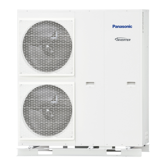
Panasonic WH-MHF09G3E5 Service Manual
(mono bloc) air-to-water heatpump system
Hide thumbs
Also See for WH-MHF09G3E5:
- Service manual (138 pages) ,
- Operating instructions manual (100 pages) ,
- Planning and installation manual (224 pages)
Table of Contents
Advertisement
Quick Links
This service
information is
designed for e
It does not c
ontain warning
gs or cautions t
Products pow
wered by elect
tricity should be
service or re
epair the produc
ct or products d
There are s
special compon
nents used in th
Diagrams, C
Circuit Board Di
iagrams, Explod
with manuf
facturer's specif
fied parts to pr
manufactur
rer.
In ord
der to avoid fro
stbite, be assu
WARNIN
experienced rep
pair technicians
to advise non-t
technical individ
e serviced or re
epaired only by
dealt with in th
is service infor
IMPORT
TANT SAFE
his equipment w
which are impo
ded Views and R
Replacement P
revent shock, f
ire or other ha
PRECAUT
TION OF LOW
red of no refrig
gerant leakage
NG
s only and is n
ot designed for
duals of potent
tial dangers in
y experienced
professional te
rmation by anyo
one else could
ETY NOTIC
CE
rtant for safety.
. These parts a
arts List. It is es
ssential that the
zards. Do not
modify the orig
TEMPERATU
RE
during the inst
tallation or repa
Order No
o. PAPAMY150
Mono
o Bloc U
WH-M
MHF09G
G3E5
WH-M
MHF12G
G6E5
Destina
D
Eur
Tur
r use by the ge
eneral public.
attempting to s
service a produ
echnicians. Any
y attempt to
d result in serio
us injury or dea
are marked by
in the Schem
!
se critical parts
should be repla
ginal design wit
thout permissio
airing of refrige
erant circuit.
© Panaso
onic Corporation
06105CE
Unit
tion
rope
rkey
uct.
ath.
matic
aced
on of
n 2015.
Advertisement
Table of Contents

Summary of Contents for Panasonic WH-MHF09G3E5
- Page 1 Order No o. PAPAMY150 06105CE Mono o Bloc U Unit WH-M MHF09G G3E5 WH-M MHF12G G6E5 Destina tion rope rkey WARNIN This service information is designed for e experienced rep pair technicians s only and is n ot designed for r use by the ge eneral public.
-
Page 2: Safety Precautions
1. Safety Precautions Read the following “SAFETY PRECAUTIONS” carefully before installation of (Mono bloc) Air-to-Water Heatpump system (hereafter referred to as “Mono bloc unit”). Electrical works and water installation works must be done by licensed electrician and licensed water system installer respectively. - Page 3 WARNING This equipment is strongly recommended to be installed with Residual Current Device (RCD) on-site according to the respective national wiring rules or country-specific safety measures in terms of residual current. The unit is only for use in a closed water system. Utilization in an open water system may lead to excessive corrosion of the water piping and risk of incubating bacteria colonies, particularly Legionella, in water.
-
Page 4: Specifications
2. Specifications WH-MHF09G3E5 Item Unit Refrigerant System Performance Test Condition EN14511 Condition A7W35 A2W35 (Ambient/Water) 9.00 9.00 Heating Capacity BTU/h 30700 30700 kcal/h 7740 7740 4.64 3.45 kcal/hW 3.99 2.97 Air Flow /min (ft /min) 76.8 (2710) Refrigeration Control Device... - Page 5 Item Unit Mono Bloc Unit Power factor means total figure of compressor and outdoor fan motor. Number of core Power Cord Length m (ft) Thermostat Electronic Control Protection Device Electronic Control Item Unit Water System Performance Test Condition EN14511 Outdoor Ambient °C -20 ~ 35 Operation Range...
- Page 6 3. Features Inverter Technology - Energy saving High Efficiency Compact Design Environment Protection - Non-ozone depletion substances refrigerant (R407C) Easy to use remote control Weekly Timer setting Quality Improvement - Random auto restart after power failure for safety restart operation - Gas leakage protection - Prevent compressor reverse cycle - Inner protector to protect compressor...
-
Page 7: Location Of Controls And Components
4. Location of Controls and Components Mono Bloc Unit Air inlet (rear) Top Plate Air inlet (side) Cabinet Front Plate Air outlet Handle (2 pieces front and 2 pieces behind) - Page 8 4.1.1 Main Components (VIEW WITHOUT COVER) DETAIL A g DETAIL A h WH-MHF12G6E5 WH-MHF09G3E5 (WITHOUT OLP (WITHOUT OLP COVER) COVER) View without cabinet top plate Optional cord / cable :- • Power Supply 1 3-way Valve cable (3 x min 0.5mm •...
- Page 9 5. Dimensions Mono Bloc Unit <Top View> (579) <Front View> <Side View> <Side View> 1283 (30) 318.5 <Back View> Unit: mm 83.5...
-
Page 10: Refrigeration And Water Cycle Diagram
6. Refrigeration and Water Cycle Diagram Outdoor Side Mono bloc Unit Water Pressure Gauge Expansion Liquid Vessel Water Capillary Side Flow Expansion Tube (3-Way Switch Valve Strainer Strainer Valve) Subcooler Water Inlet (Connect Water Pump Sanitary Pipe Tank) Temp. Expansion Strainer Pipe Sensor... - Page 11 WH-MHF12G6E5...
-
Page 13: How To Adjust Water Flow Rate
Before adjust the water flow rate, make sure that the total water volume in the installation is 50 litres minimum for heating side. The default setting is SPEED 4 (Only for WH-MHF09G3E5) and SPEED 5 for WH-MHF12G6E5. Please ensure the minimum flow rate is not less than 13 l/min and not more than 50 l/min. - Page 14 18.1.2 WH-MHF12G6E5 Heating Characteristics at Different Outdoor Air Temperature Condition Outdoor air temperature : 7°C (DBT), 6°C (WBT) Indoor water inlet temperature : 30°C Indoor water outlet temperature : 35°C 14.000 13.000 12.000 11.000 10.000 9.000 Outdoor Temperature (°C) 6.500 5.500 4.500...
-
Page 15: Heating Capacity Table
18.2 Heating Capacity Table 18.2.1 WH-MHF09G3E5 Water 65** Out (°C) Input Input Input Input Input Input Outdoor Capacity Capacity Capacity Capacity Capacity Capacity Power Power Power Power Power Power Air (°C) 9000 3460 9000 3710 9000 4010 8800 4260 8500...


