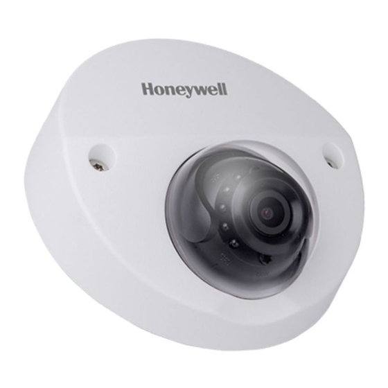
Honeywell Performance Series Quick Installation Manual
Wdr 1080p people counting camera
Hide thumbs
Also See for Performance Series:
- User manual (276 pages) ,
- Owner's manual (22 pages) ,
- Installation instructions manual (16 pages)
Advertisement
Quick Links
H2W2PC1M WDR 1080P People Counting
Camera
Quick Installation Guide
Thank you for purchasing a Honeywell Performance Series IP camera. Follow
the instructions in this guide to install and log in to your camera. For
instructions on configuring the camera, refer to the user guide on the CD that
came with your camera. If you require additional assistance, call the number
listed for your region on the back cover.
Cautions and Warnings
CAUTION
RISK OF ELECTRIC
SHOCK
DO NOT OPEN
CAUTION: TO REDUCE THE RISK OF ELECTRIC
SHOCK, DO NOT REMOVE THE COVER.
NO USER-SERVICEABLE PARTS INSIDE.
REFER SERVICING TO QUALIFIED SERVICE
PERSONNEL.
WARNING
To ensure compliance with electrical safety standards, this product is intended for
use with a Listed Power Adapter marked "Limited Power Source" or "LPS" on the
unit, output rated to 12 VDC, minimum 0.33 A, TMA=60 deg C, or from Power over
Ethernet (PoE) provided by Listed Information Technology Equipment meeting IEEE
802.3af PoE standard.
CAUTION
The Ethernet connection is not intended to be connected to exposed (outside plant)
networks. Do not connect two power sources to the camera at the same time.
CAUTION
Invisible LED radiation (850 nm). Avoid exposure to beam.
Important Safeguards
•
Read and keep these instructions.
•
Do not aim the camera toward a bright light source for extended periods to prevent damage to the
imager. Avoid operating the unit under or close to unstable light sources (may cause flickering), or
close to fluorescent lamps or objects reflecting light.
•
Do not touch the camera lens.
•
Do not drop the camera or subject it to physical shock.
•
Do not use a strong or abrasive detergent when cleaning the camera.
•
Avoid operating or storing the unit in extremely humid, dusty, hot/cold environments, where the
operating temperature is outside the recommended range of -22°F to 140°F (–30°C to 60°C).
•
Do not apply power to the camera before completing installation.
•
Ensure that the installation surface can support at least three times the weight of the camera.
THIS SYMBOL INDIC ATES THAT
DANGEROUS VOLTAGE
CONSTITUTING A RISK OF
ELECTRIC SHOCK IS PRESENT
WITHIN THE UNIT.
THIS SYMBOL INDIC ATES THAT
IMPORTANT OPERATING AND
MAINTENANCE INSTRUCTIONS
ACCOMPANY THIS UNIT.
Before You Begin
Before you begin, check that you have received all the parts listed below. If any parts are missing or
damaged, contact your dealer immediately.
• Camera
• Self-tapping screws (×4)
• Installation CD
• Plastic wall anchors (×4)
• Quick installation guide
• Mounting template
• Allen key (L-wrench)
CAUTION
Installation and servicing should be performed only by qualified and experienced technicians
to conform to all local codes and to maintain your warranty.
Preparing the Mounting Surface
1.
Inspect the site where you want to install the camera. The mounting
surface must be flat and capable of supporting at least three times
the weight of the camera.
2.
Remove the backing from the mounting template sticker and affix the
sticker to the mounting surface.
Note If you are using the side exit for the cable, note the orientation of the
cable exit notch. In outdoor installations, the notch should point
downwards to prevent water from entering the camera housing.
3.
Drill screw holes at the locations indicated on the mounting template
sticker and insert the supplied plastic anchors in the holes.
4.
If you are flush mounting the camera and want to store the cables
inside the wall or ceiling, drill a hole at the cable exit position on the
mounting template and then pull the cables through the hole.
Mounting the Camera
Direction of Camera
The camera should be mounted overhead and the lens should point 90°, straight down with stable
and bright lighting to guarantee the performance.
The ideal installed height is between 2.9m to 3.3m with no lens obstruction. See figure below:
Out
In
Advertisement

Summary of Contents for Honeywell Performance Series
- Page 1 Installation and servicing should be performed only by qualified and experienced technicians to conform to all local codes and to maintain your warranty. Thank you for purchasing a Honeywell Performance Series IP camera. Follow the instructions in this guide to install and log in to your camera. For Preparing the Mounting Surface instructions on configuring the camera, refer to the user guide on the CD that...
- Page 2 Document 800-24587 – Rev B – 10/2018 © 2018 Honeywell International Inc. All rights reserved. No part of this publication may be reproduced by any means without written permission from Honeywell. The information in this publication is believed to be accurate in all respects. However, Honeywell...


