Table of Contents
Advertisement
Advertisement
Table of Contents

Summary of Contents for Honeywell INTUVUE RDR-7000
- Page 1 INTUVUE RDR-7000 WEATHER RADAR SYSTEM QUICK START GUIDE...
-
Page 2: Safety Instructions
SAFETY INSTRUCTIONS • Ensure that there is sufficient space on all sides while working. • Protect the device from direct sunlight. WARNING Advisory circular 20.68B defines minimum safe levels of RF energy radiation. The RF energy radiated by the RDR-7000 weather radar system is low level. •... -
Page 3: Technical Support
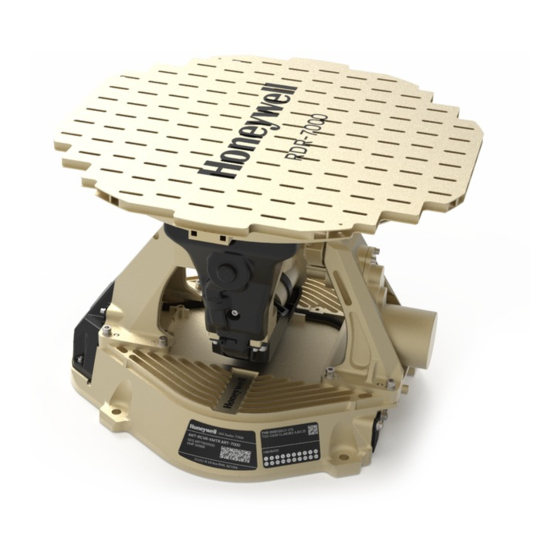
Where can I find the RDR-7000 installation manual and other documentation? Access Honeywell technical publications at aerospace2.honeywell.com/wps/myportal/tech-pubs Where can I purchase upgraded software features for the RDR-7000? Visit our RDR-7000 product page for more information purchasing additional features at aerospace.honeywell.com/en/learn/products/weather-radar/rdr-7000. - Page 4 OVERVIEW FP 7000 (Antenna) 8 captive screws for antenna mounting ART 7000 Guide pin receivers for backshell RJ45 connector SD card slot Bulkhead Spacer Bulkhead spacer hardware...
- Page 5 WIRING The RDR-7000 is designed to be a drop-in replacement for existing Primus radar systems; no wiring changes should be required in this scenario. Updated installations using Real-Beam Maritime and/or 3D Volumetric Buffer may require additional wiring. NOTE Refer to the full RDR-7000 installation manual and/or the appropriate STC for instructions on how to complete the wiring.
-
Page 6: Radar Installation
RADAR INSTALLATION Move the ART-7000 to the open radome. For 18” antenna systems, align the 1-inch spacer behind the ART-7000, if necessary. Hold the assembled unit along with the 1-inch spacer firmly in position on the nose bulkhead mounting plate and attach with four through bolts. •... -
Page 7: Software Configuration
A software configuration file must be uploaded to the RDR-7000 to operate the radar successfully. Create SW configuration file Visit Honeywell Aerospace Software & Data Services at ads.honeywell.com. Select "Custom Software and EMS" and then "RDR-7000". Follow the instructions to create and download a SW configuration file. - Page 8 Power up the radar. If the SD card contains valid files, uploading will commence. Observe the LED to determine the success of the uploading operation. • Flashing Green = In progress • Green = Data fully loaded • Yellow = Invalid SD card or contents •...
- Page 9 TESTING Ensure that all personnel are a safe distance from the radar. Power up the radar. Select TEST from the Controller or the Aircraft Maintenance System. Confirm that the color test pattern is displayed on the radar display. Allow approximately 60 seconds for TEST to finish. Verify that no errors are reported by the technician at the Controller or the Aircraft Maintenance System;...

