Advertisement
Quick Links
PART 1 - GENERAL
1.0 Scope
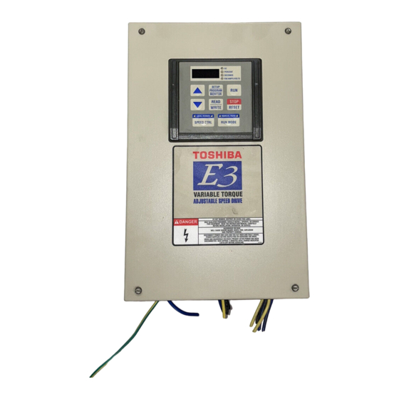
This specification shall cover Toshiba E3 AC Variable Frequency Drives, 6 pulse for
230V and 460V.
1.1 References
A. National Electric Manufactures Association (NEMA)
B. Underwriters Laboratories, Inc. (UL) and CSA
C. National Electric Code (NEC)
D. IEEE 519. Compliance of IEEE 519 can be determined after Toshiba performs a
harmonics analysis. The analysis will be done after we receive a completed
harmonics questionnaire.
E. ISO 9001
1.2 Submittal
Submittals shall include Toshiba standard operation manual. Schematics can be obtained
from factory upon request.
PART 2 – E3 VARIABLE FREQUENCY DRIVE
2.0 General
A. This specification covers AC adjustable frequency drives for HVAC applications.
B. The manufacturer shall not have less than fifteen years of experience in the
manufacture of VFD's.
C. The manufacturer shall manufacture both AC drives and motors at the same
facility.
D. The drive shall be manufactured in the United States.
2.1 Design Criteria
A. The drive should be a PWM (Pulse Width Modulated) transistorized inverter
using IGBT's (Insulated Gate Bipolar Transistors) and must be fully digital.
E3 Adjustable Speed Drive
Engineering Specification
1
Advertisement

Summary of Contents for Toshiba E3
- Page 1 E3 Adjustable Speed Drive Engineering Specification PART 1 - GENERAL 1.0 Scope This specification shall cover Toshiba E3 AC Variable Frequency Drives, 6 pulse for 230V and 460V. 1.1 References A. National Electric Manufactures Association (NEMA) B. Underwriters Laboratories, Inc. (UL) and CSA C.
- Page 2 B. The drive shall utilize Insulated Gate Bipolar Transistor (IGBT’s) in its power section. C. The E3 VFD shall have 3 basic design criteria Rectifier Section that shall include diode bridge rectifier to convert AC to Filtering Section that shall include capacitors to eliminate “ripple” affect on the DC bus to produce smooth DC bus voltage.
- Page 3 M. The drive shall have an adjustable retry function after a fault. Both number of attempts (at least 10) and time between (1-10 sec). N. The drive shall have an adjustable output short circuit detection selection for standard motor and high-speed motors (very low inductance). O.
- Page 4 I. The drive shall have adjustable UL listed electronic overload protection (10% - 100%). J. The drive shall have a custom programmable volt/hertz pattern. 2.5 Input / Output Capabilities A. The drive shall accept the following frequency commands signals: 1) 3kΩ potentiometer (1kΩ to 10KΩ potentiometer connection also possible) 2) 0 to 10 Vdc (Input impedance Zin:33kΩ) 3) 0 to ±...
- Page 5 3) Over current during normal run trip 4) Over current on the DC Bus during acceleration trip 5) Over current on the DC Bus during deceleration trip 6) Over current on the DC Bus during normal run trip 7) Load end over current trip detected at start-up (output terminals, motor wiring, etc.) 8) U-phase short circuit trip detected at start-up 9) V-phase short circuit trip detected at start-up...
- Page 6 C. Isolated input and output transducers are available upon request. D. All drives regardless of size/voltage should have isolated bypass capability as an available option. E. 600V, E3 drives are also available from 5HP to 125HP. The ratings shall be 540V-660V/60 Hz for 600V models. Communication options to include:...
- Page 7 2.9 Drive Environmental Conditions A. Environment - Indoors NEMA 1 metal enclosure, plastic shall not be acceptable. B. Ambient temperature - 14°F to 104°F (up to 122°F with cover removed). C. Altitude - 3,300 feet maximum without derating. D. Relative humidity - 95% maximum (no condensation allowed). E.


