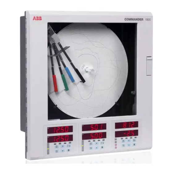
ABB C1900 Operating Instructions Manual
Circular chart recorder
Hide thumbs
Also See for C1900:
- Operating manual (44 pages) ,
- Installation manual (28 pages) ,
- User manual (20 pages)
Table of Contents
Advertisement
Quick Links
—
A B B M E A S U R E M E N T & A N A LY T I C S | O P E R AT I N G I N S T R U C T I O N | D A I R Y FA R M S U P P L E M E N T
C1900
Circular chart recorder
For more information
—
C1900
Further publications are available for free download
circular chart recorder
from:
www.abb.com/recorders
or by scanning this code:
Measurement made easy
C1900
Circular chart recorder
Datasheet
C1900
Circular chart recorders and
recorder / controllers
Installation Guide
C1900
Circular chart recorders
Operating Guide
C1900
Circular chart recorder / controllers
Operating Guide
C1900
Circular chart recorders
Programming Guide
C1900
Circular chart recorder / controllers
Programming Guide
Search for or click on
DS/C1900R-EN
IM/C1900-INS
IM/C1900-OGR
IM/C1900-OGC
IM/C1900-PGR
IM/C1900-PGC
Advertisement
Table of Contents

Summary of Contents for ABB C1900
- Page 1 A B B M E A S U R E M E N T & A N A LY T I C S | O P E R AT I N G I N S T R U C T I O N | D A I R Y FA R M S U P P L E M E N T C1900...
- Page 2 Use of Instructions Health and Safety To ensure that our products are safe and without risk to health, Warning – an instruction that draws attention to the risk of injury or death. the following points must be noted: • The relevant sections of these instructions must be read Caution –...
-
Page 3: Table Of Contents
1.1 About this Manual About this Manual............. 1 This Supplementary Manual provides an overview of the use of the C1900 Circular Chart Recorder on a Dairy Farm and Application Overview ..........2 describes the electrical connections and special alarm feature designed for this application, together with chart and pen ELECTRICAL INSTALLATION .......... -
Page 4: Application Overview
Under normal conditions the storage tank is empty and at ambient temperature when the milking system is started. In a dairy application, the C1900 Circular Chart Recorder Once there is sufficient milk in the storage tank (normally monitors the milking system cooling and washing cycles for... - Page 5 Residence Warning Lights (Optional) White Barn Warning Lights C1900 Connections A – Analog input connection from tank RTD sensor B – Analog input connection from return flowline RTD sensor C – Digital input connection from refrigeration power (refrigeration ON signal) D –...
-
Page 6: Electrical Installation
2 ELECTRICAL INSTALLATION 2.1 Electrical Connections – Figs. 2.1 to 2.3 Warning. Before making any connections, ensure that the power supply, any high voltage-operated control circuits and high common mode voltages are switched off. Note. • Use flexible conduit for cable routing (signal and power). - Page 7 2 ELECTRICAL INSTALLATION …2.1 Electrical Connections – Figs. 2.1 to 2.3 High Voltage Digital Interface Card (See Fig. 2.1 for cover removal details) Terminal Block 1 Channel 1 (Red) T E R L IV M IN Terminal Block 2 Channel 2 (Green) Milking System Terminal Block 1 ON Signal...
-
Page 8: Setting Up
Rotate chart to align the time line with the red pen (see also IM/C1900-OGR Fig. 2.1 Remove cap IM/C1900-OGC Fig. 2.1) Lower the chart clamp and press down firmly to ensure that the 2... -
Page 9: Alarms
4 ALARMS Note. Refer to Programming Guide (IM/C1900–PGR or IM/C1900–PGC) Section 3.4 for alarm configuration procedures. 4.1 Delayed High/Low Process Alarm – Fig. 4.1 The operation of a Delayed High/Low Process Alarm is identical to that of the Standard High/Low Process Alarm but the alarm can be enabled/disabled by use of a digital signal. -
Page 10: Configuration
5 CONFIGURATION 5.1 Default Configuration 1 – 1 – t l i 1 – 1 – 1 – . t r – – – – – – . n i . n i – – – – v i t –... - Page 11 Sales Service Software...
- Page 12 We reserve the right to make technical changes or modify the contents of this document without prior notice. With regard to purchase orders, the agreed particulars shall prevail. ABB does not accept any responsibility whatsoever for potential errors or possible lack of information in this document.


